 ]
]A transcription of Richard F. Bond's "Description of Bond's Isodynamic Escapement for Astronomical Clocks" reprinted from Brunnow's Astronomical Notices, Boston, October 1860
Note: Editorial material has been added in [square brackets].
[Cover of this offprint from 1860]
DESCRIPTION OF
BOND'S
ISODYNAMIC ESCAPEMENT
for
Astronomical Clocks
FROM "BRUNNOW'S ASTRONOMICAL NOTICES," OCTOBER, 1860
BOSTON, 1860.
[Page 1]
IN giving the description of my Isodynamic Escapement, it will be necessary, in order to explain its advantages fully, to give some count of those now in use and of the obstacles still remaining to be overcome in order to obtain one perfectly exact.
The advantages to be derived from the possession of a clock of perfect accuracy (were such a thing possible), could hardly be overestimated. The science of Astronomy, in particular, would receive important benefits from such an instrument. But as no timekeeper has ever yet been constructed that could be relied upon as being absolutely free from error, it is evident that there is still room for improvement. The sources of irregularity have long engaged the attention of many able scientific investigators, and very numerous contrivances for counteracting them have been suggested. These remarks refer, of course, only to such timekeepers as have the pendulum for their regulator, and indeed, no other natural principle is practically so well adapted to produce regularity.
The end to be attained is to keep the pendulum vibrating always in the same arc, always encountering the same amount of resistance and of motive power.
The principal errors may be divided into two classes, those arising from the mechanical intervention necessary to maintain the vibratory motion of the pendulum, and those arising from such causes as would still affect it, provided its vibration could be maintained by a uniform force; for instance, changes of temperature, the barometer and hygrometer, magnetic influences, and to a slight degree, the position of the moon. By far the most important of these errors are those arising from the friction influencing the pendulum through the escapement, as they are of such a nature as renders it almost impossible to ascertain beforehand what their influence will be, while the residuary errors of the second class are not only smaller in amount, but can, by close and accurate observation, be tabulated and the corrections applied. It is the first class, therefore, of these errors, that it is most important to remedy, and the power of doing this lies almost entirely in diminishing or equalizing the friction of
[Page 2]
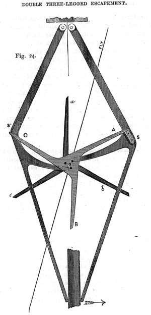
the escapement. The mere diminishing of the friction is not the only, or even the principal desideratum in such improvement; the equalizing of the force is of far more consequence, as is sufficiently proved by the single instance of the deservedly high position which Graham's escapement has so long maintained, notwithstanding the great amount of friction which it involves. One reason of its superiority to many others which boast far less actual friction, is its principle of compensating a slightly varying power upon the pallets, by a corresponding variation in the arc described by the pendulum; this has given it its practical utility. This escapement, though invented nearly a century ago, met with no successful rival, until within a few years. It has, however, recently been replaced, in some Astronomical Clocks, by Denison's three-legged gravity escapement. The superiority of this latter consists in the impulse to the pendulum being given either by the force of gravity, influenced by a small amount of friction, or by the force of a spring without such friction; but in either case there is a certain amount of variable resistance, increasing or diminishing as the wheel-work of the clock carries more or less power to the escapement, and consequently, if a heaver driving weight is applied, the pendulum encounters more friction in unlocking the escapement, without gaining any additional impulse, as it would in the case of Graham's. The vibration of the pendulum is thus affected, and its rate changed, by a varying cause, dependent upon the freedom with which the wheelwork transmits the power, and which is impossible to calculate. Notwithstanding this defect, this method has, upon the whole, smaller causes of error than any hitherto known.
[This illustration, of a "double three legged" gravity escapement is taken from A Rudimentary Treatise on Clocks and Watches and Bells, Sixth Edition. London: Lockwood & Co., 1874, by Sir Edmund Beckett (formerly E. B. Denison, later Baron Grimthorpe).
]
The Isodynamic Escapement, recently invented, overcomes entirely the difficulty of the varying power transmitted by the wheelwork, and thus obviates most of the objections to other escapements. In comparing it to previous ones, I refer only to Denison's and Graham's, they combining to a greater degree than any others the various requisites essential to a good escapement.
Besides the difficulties already enumerated, which are to be overcome in making a perfectly reliable gravity escapement, there is one which has been exceedingly troublesome, namely, the necessity of guarding against what is called tripping, or the danger of two or more teeth of the escapement wheel passing the pallets at once, when one only is intended to; this causes the hand of the clock to gain by jumps, and of course, in a most unreliable manner, while
[Page 3]
while the pendulum may be vibrating with perfect regularity. Mr. Denison, in his book on "Clock and Watch work," speaks of guarding against this difficulty as first among the essential mechanical conditions. Even in his own gravity escapement, to which I have already referred, the possibility of tripping still exists, though rendered reasonably slight by the introduction of a fan upon the escapement wheel, but in the Isodynamic Escapement, it will be seen that this danger is completely removed.
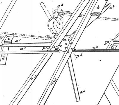
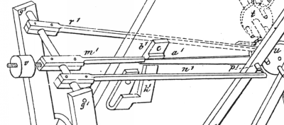
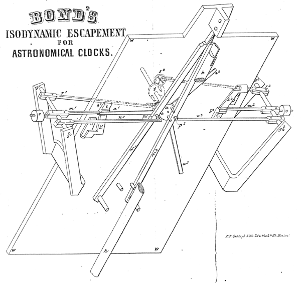
The following cut will assist in explaining the action of this contrivance.
w,
w,
w,
w,
is the back plate of the clock.
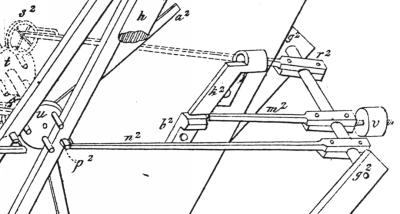
a1,
a2,
a3,
are radiating arms of very thin steel,
[Note: In the original text, the sole illustration was an engraved plate at
the end.
Because this plate, reproduced here at the end of this page,
suffers from some loss of clarity as a low-resolution digital image,
sections of it will be reproduced throughout at a higher resolution.
 ]
]
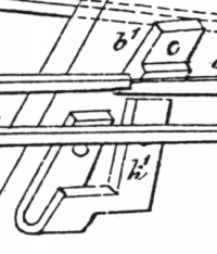
easily bending in towards the plate of the clock when they meet
the inclined planes
k1, or
k2,
[
 ]
]
though inflexible in the plane of revolution;
these arms for the escapement wheel,
which is placed outside of the clock plates,
instead of between them as is generally the case.
With a pendulum vibrating seconds,
it requires six seconds to perform an entire revolution.
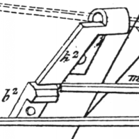
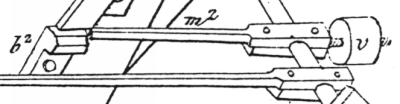
b1,
b2,
[see k1 and k2 images above]
are two blocks screwed to the plate of the clock,
projecting just so far as almost to touch the arms of the escapement wheel,
when in their natural position.
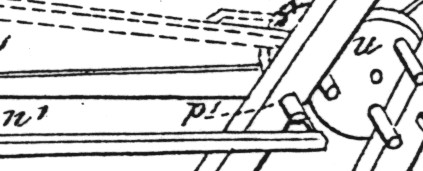
r1,
m1, and
n1,
are arms all connected firmly together through the arbor
g1,
[ ]
]
having corresponding arms
r2,
m2, and
n2,
on the other side of the clock,
similarly connected.
[ ]
]
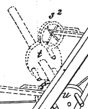
r1,
has a small friction wheel at its end,
which is alternately depressed and allowed to rise
(being slightly overbalanced),
as the pins upon the cam
t
revolve.
r2
is also acted upon by the cam,
as will be readily seen.
[ ]
]
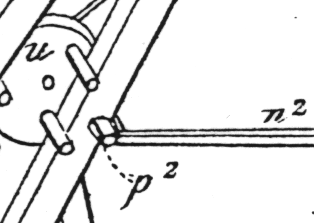
In the position shown in the cut,
the cam has raised the arm
n2,
so that a pin through its end is a little above the jewel
p2,
not touching it.
[ ]
]
m2,
is also raised in readiness to keep the arm of the escapement wheel
from springing entirely out from the block
b2,
as will be described.
[ ]
]
The pin of
n1 is prevented from rising up by the jewel
p1.
[ ]
]
f1,
f2
are the pallets.
h,
h is the pendulum.
k1,
k2
are inclined planes along which the arms of the escapement wheel slide,
before resting upon the blocks
b1,
b2.
v,
v
are balanced weights.
Suppose the parts to be in the position represented in the cut. The action will then be as follows: - the pendulum h, moving towards the left, strikes the pallet f1, carrying the jewel p1, free from the pin at the arm of n1, thus allowing n1, which is overbalanced by the counterpoise v, to escape upwards; this carries with it the arm m1, which is attached to the same arbor g1; this unlocks a1,
[Page 4]
and allows it to spring out from the fixed block b1. The escapement wheel, being now free, makes one sixth of a revolution, and in doing so, brings the cam into such a position as to allow the pin of the arm n2, to fall upon the jewel p2. In revolving, the arm a2 slides down the inclined plane k2, which bends it, as it advances, slightly inward toward the plate of the clock, so that it falls upon the block b2; when, no longer influenced by the inclined plane, it springs out to regain its natural position, but is met, and prevented from entirely leaving the block by the arm m2, which keeps its position so long as the arm n2 is prevented from falling from the jewel p2. The pendulum, now vibrating to the right, moves the pallet f2, so as to allow the arm n2 to drop, carrying with it the arm m2, thereby releasing the arm of the escapement wheel a2, which again makes one-sixth of a revolution, and is stopped by a2 passing up the inclined plane k1, and being held upon the block b1, by the arm m1, as a1 is shown to be in the cut. The same operations are repeated with each vibration of the pendulum.
In this escapement the cam plays a very important part in replacing the detent arms, m1, m2, n1, n2, in the proper positions to be again unlocked by the pallets, as the pendulum vibrates. The only two places where any friction which influences the pendulum occurs, are upon the jewels p1 and p2. Practically, however, the amount is so trifling as to be almost inappreciable, being found by actual experiment to be less than one-twentieth of that which takes place in a marine chronometer, and incomparably less than in any other clock escapement, of which I have any knowledge.
The chief excellence of this invention consists in this friction, slight as it is, being constant, and entirely uninfluenced by the wheelwork; indeed, the power may be increased to a hundred times the amount necessary to drive the clock, supposing the machinery capable of sustaining the weight, without in the least increasing the friction of the pendulum, or in any way interfering with the extent or time of its vibration. After a long and careful trial, I am satisfied that this is a more reliable and accurate escapement than any that have been made public.
After this escapement had been perfected, I found, that by a very simple addition, I could secure a magnetic break-circuit entirely free form the danger of oxidization, and which would not in any way influence the pendulum, or disadvantageously impede any of the other mechanism of the clock, hitherto the chief drawbacks to all other break-circuits. It is sufficient proof of its certainty to say, that it has been in operation for a year past without adjustment or alteration, never having been known to fail in any one instance.
Astronomers, in particular, may, I hope, benefit by this invention, as the difficulty of finding a break-circuit that would not require constant care and alteration, has long been a serious evil to them in recording their observations by the method (now general) of electro-magnetic registration.
RICHARD F. BOND
[Plate]
F.F.Oakley's Lith 204 Wash.n St. Boston
Presented originally by lemur.com.SM